USART
The microcontroller has a peripheral called USART, which stands for Universal Synchronous/Asynchronous Receiver/Transmitter. This peripheral can be configured to work with several communication protocols like the serial communication protocol.
Throughout this chapter, we’ll use serial communication to exchange information between the microcontroller and your computer. But before we do that we have to wire up everything.
I mentioned before that this protocol involves two data lines: TX and RX. TX stands for transmitter and RX stands for receiver. Transmitter and receiver are relative terms though; which line is the transmitter and which line is the receiver depends from which side of the communication you are looking at the lines.
Newer board revisions
If you have a newer revision of the board and are using the on-board USB <->
Serial functionality then the auxiliary crate will set pin PC4 as the TX
line and pin PC5 as the RX line.
If you had previously connected the PC4 and PC4 pins in order to test the loopback functionality in the previous section, make sure to remove that wire, or the upcoming serial communication will fail silently.
Everything is already wired on the board so you don’t need to wire anything yourself. You can move on to the next section.
Older board revisions / external serial module
If you are using an external USB <-> Serial module then you will need to
enable the adapter feature of the aux11 crate dependency in Cargo.toml.
[dependencies.aux11]
path = "auxiliary"
# enable this if you are going to use an external serial adapter
features = ["adapter"] # <- uncomment this
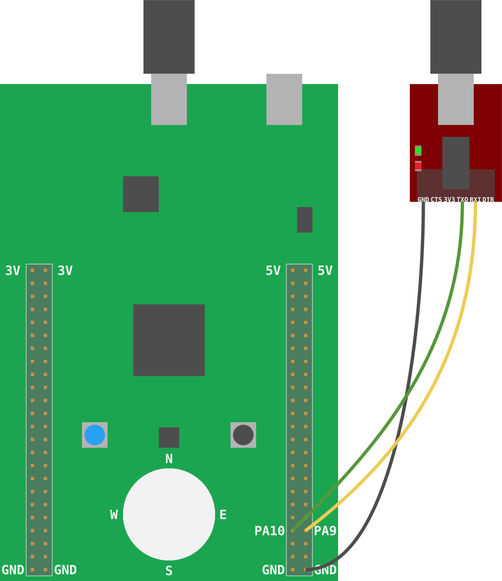
We’ll be using the pin PA9 as the microcontroller’s TX line and PA10 as its RX line. In other
words, the pin PA9 outputs data onto its wire whereas the pin PA10 listens for data on its
wire.
We could have used a different pair of pins as the TX and RX pins. There’s a table in page 44 of the Data Sheet that list all the other possible pins we could have used.
The serial module also has TX and RX pins. We’ll have to cross these pins: that is connect the microcontroller’s TX pin to the serial module’s RX pin and the micro’s RX pin to the serial module’s TX pin. The wiring diagram below shows all the necessary connections.

These are the recommended steps to connect the microcontroller and the serial module:
- Close OpenOCD and
itmdump - Disconnect the USB cables from the F3 and the serial module.
- Connect one of F3 GND pins to the GND pin of the serial module using a female to male (F/M) wire. Preferably, a black one.
- Connect the PA9 pin on the back of the F3 to the RXI pin of the serial module using a F/M wire.
- Connect the PA10 pin on the back of the F3 to the TXO pin of the serial module using a F/M wire.
- Now connect the USB cable to the F3.
- Finally connect the USB cable to the Serial module.
- Re-launch OpenOCD and
itmdump
Everything’s wired up! Let’s proceed to send data back and forth.